Professional & university work

Engineering Projects

Power systems, power electronics, and embedded design. Modelled, wired, instrumented, and tested.

Summer 2026

Typhoon HIL

Energy & Power Electronics Systems

Second internship on the Energy & Power Electronics Systems team, integrating ComAp InteliGen 1000, InteliNeo 6000 and InteliMains 1010 controllers into hardware-in-the-loop testbeds. That meant wiring binary and analog I/O, emergency stop, CT and VT secondaries, and BESS, mains and bus voltages through Universal HIL Connect, then building the signal and channel mapping programmatically so probes and terminals generate themselves instead of being placed by hand. The work also covered converting PSCAD components into Typhoon models and EV charger testing across the NACS and CCS standards.

  • ComAp InteliGen 1000
  • InteliNeo 6000
  • InteliMains 1010
  • Universal HIL Connect
  • Binary & analog I/O
  • CT / VT secondaries
  • PSCAD conversion
  • EV charging, NACS / CCS
Animation of a PSCAD voltage source component being converted into its Typhoon equivalent
PSCAD source converted into a Typhoon component
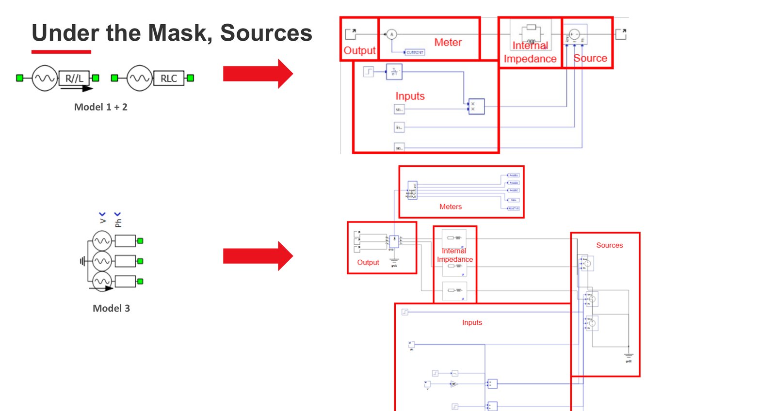
Source component internals showing the output, meter, internal impedance, source and input blocks under the mask
Under the mask, source model internals
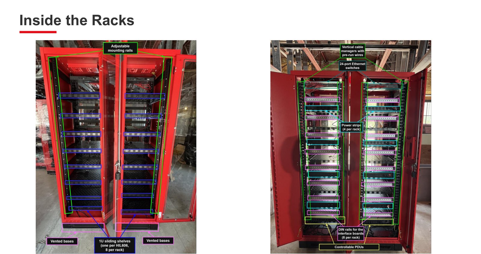
Two rack interiors annotated with mounting rails, sliding shelves, cable managers, Ethernet switches, power strips and DIN rails
Inside the racks, front and rear build out
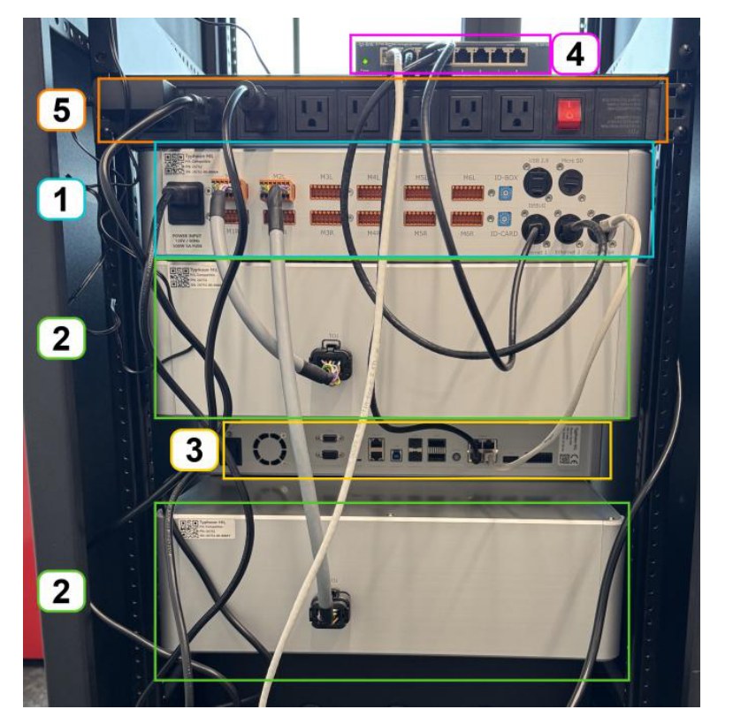
Rear of the inverter rack showing power distribution, network switch and data cabling
Inverter rack rear, power and data
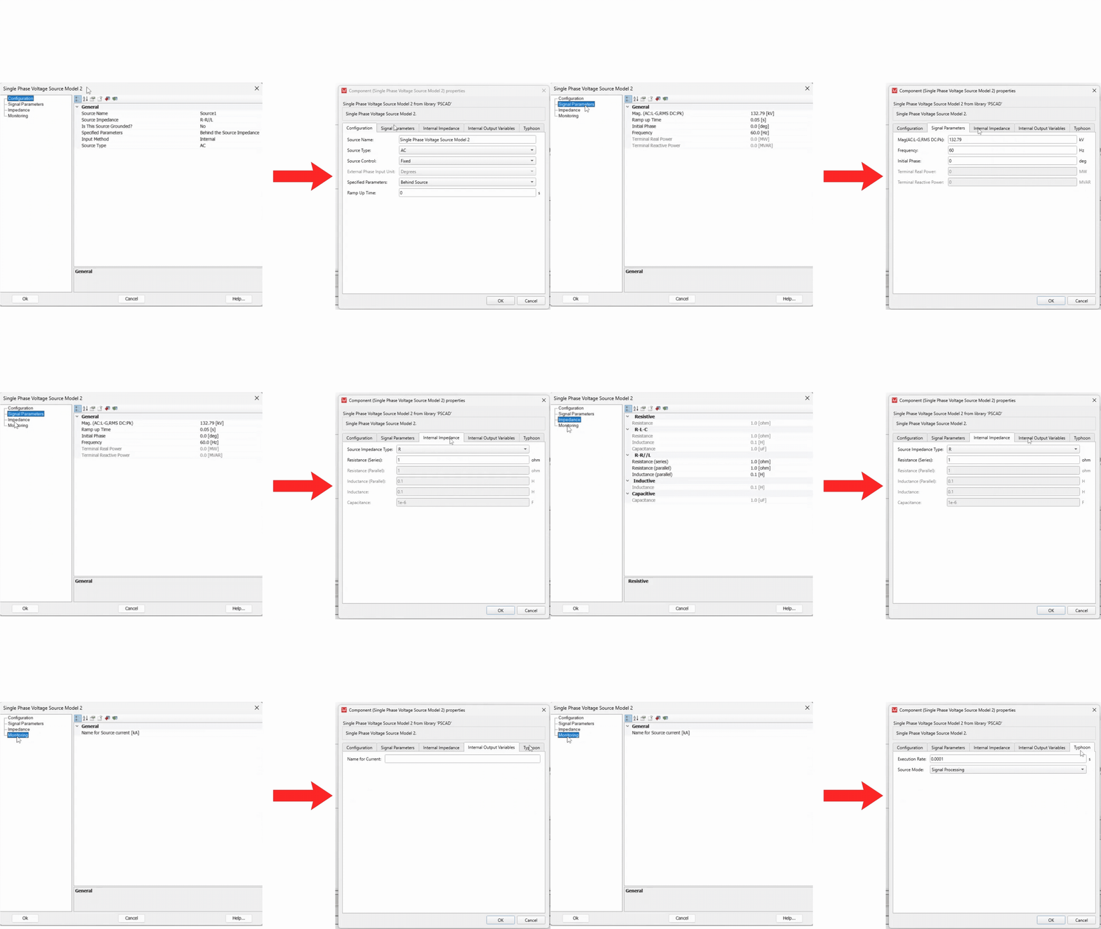
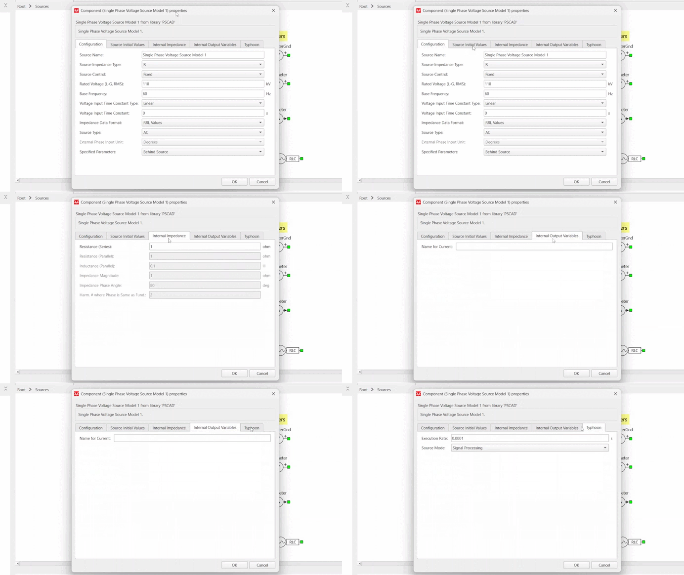
Animation cycling through the configuration, source initial values, impedance and output variable tabs of a converted component
Every parameter tab carried across
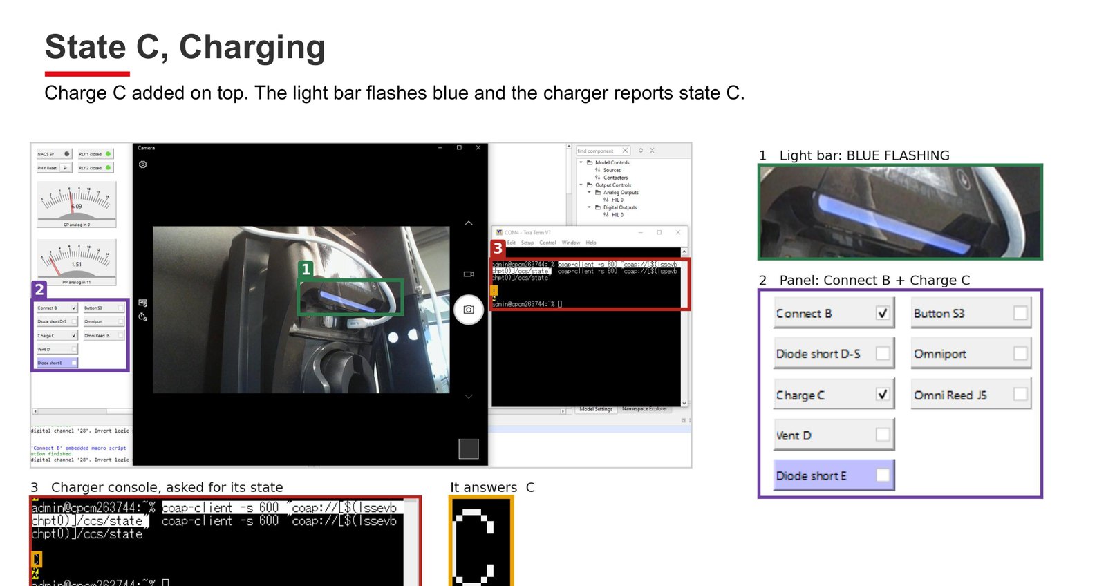
EV charger under test with the light bar flashing blue, the control panel set to connect and charge, and the charger console reporting state C
EV charger in state C, driven and read back over CoAP

Some details are redacted for confidentiality.
Summer 2025

Typhoon HIL

Energy & Power Electronics Systems

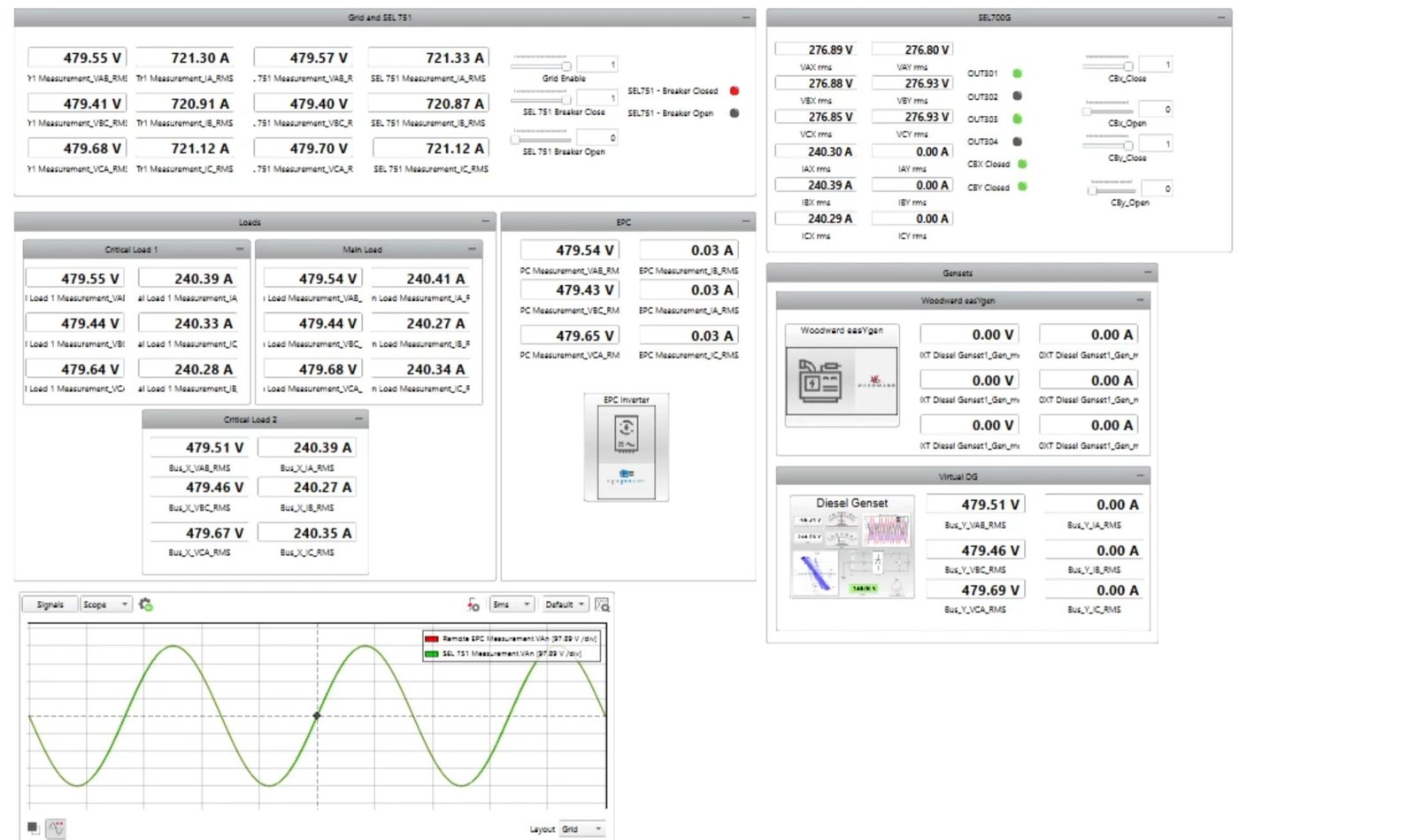
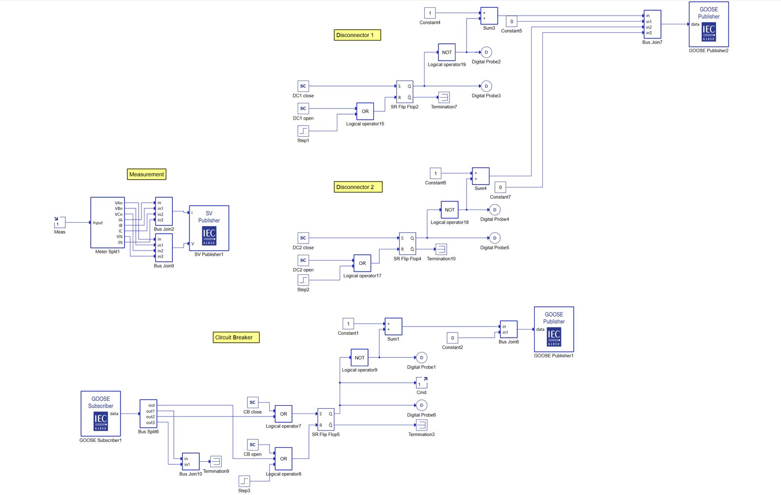
First internship on the same team, building and extending microgrid testbeds on Typhoon HIL's real-time simulation platform. The models carry IEC 61850 GOOSE and Sampled Values messaging between simulated breakers, disconnectors and metering, with SEL 751 and SEL 700G protective relays in the loop alongside a Woodward easYgen genset controller and an EPC inverter. The SCADA interfaces built on top drove live demonstrations that were used in customer engagements.

  • Hardware-in-the-loop
  • IEC 61850 GOOSE
  • Sampled Values
  • SEL 751 / SEL 700G
  • Microgrid modelling
  • SCADA
  • Real-time simulation
SCADA panel showing bus voltages and currents for grid, loads, gensets and inverter
Microgrid SCADA with live voltages, currents and breaker states
Model of GOOSE publisher and subscriber blocks driving breaker and disconnector logic
IEC 61850 GOOSE publish and subscribe, breaker logic
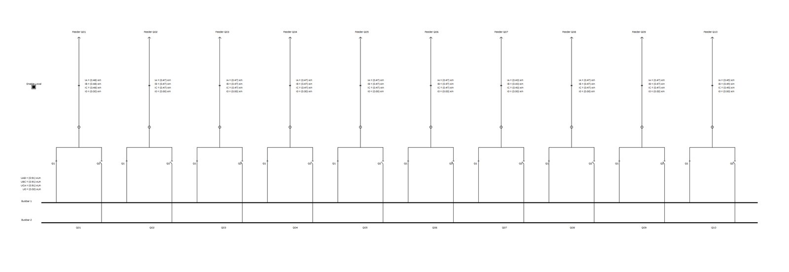
Single line diagram of ten feeders across two busbars
Ten feeder distribution model across two busbars

Some details are redacted for confidentiality.
Integrated Design Project

Autonomous Wireless Sensor Node

Virginia Tech

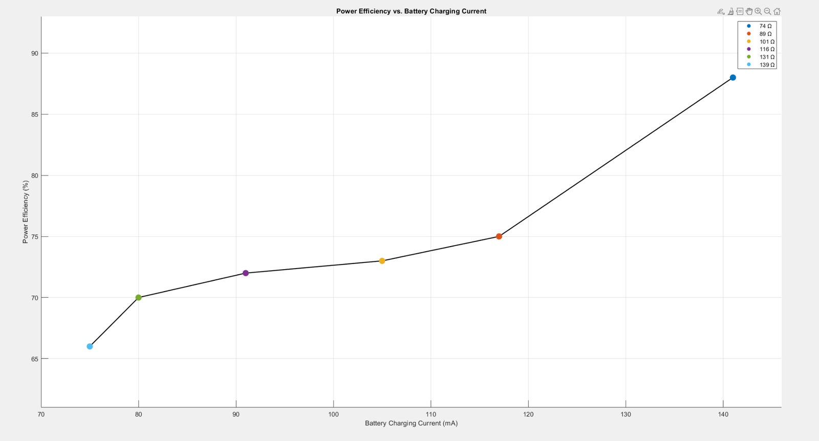
A solar powered wireless sensor node designed for long term unattended deployment. An Arduino driven boost converter with closed loop feedback charges a 9 V battery, a thermistor handles temperature sensing, and Bluetooth transmits readings out. The converter was characterised across six load resistances and reached 88% power efficiency at its highest charging current, and when solar input is lost the node drops into a sleep mode that stretches runtime past five days on battery alone.

  • Boost converter
  • Closed loop feedback
  • Solar charging
  • Thermistor sensing
  • Bluetooth telemetry
  • Low power sleep
Chart of power efficiency against battery charging current across six load resistances
Power efficiency against charging current, 66% to 88% across load
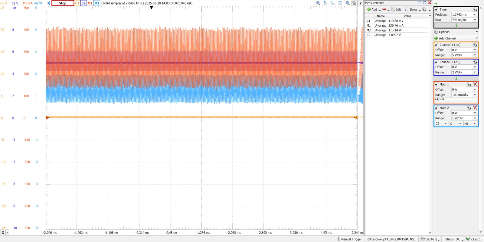
Instrument capture showing converter voltage, current and computed power
Converter capture at 4.90 V, 240 mA, 1.17 W average

Some details are redacted for confidentiality.
2025 & 2026

Collegiate Wind Competition

Wind Turbine Team at Virginia Tech
Power Systems & Controls

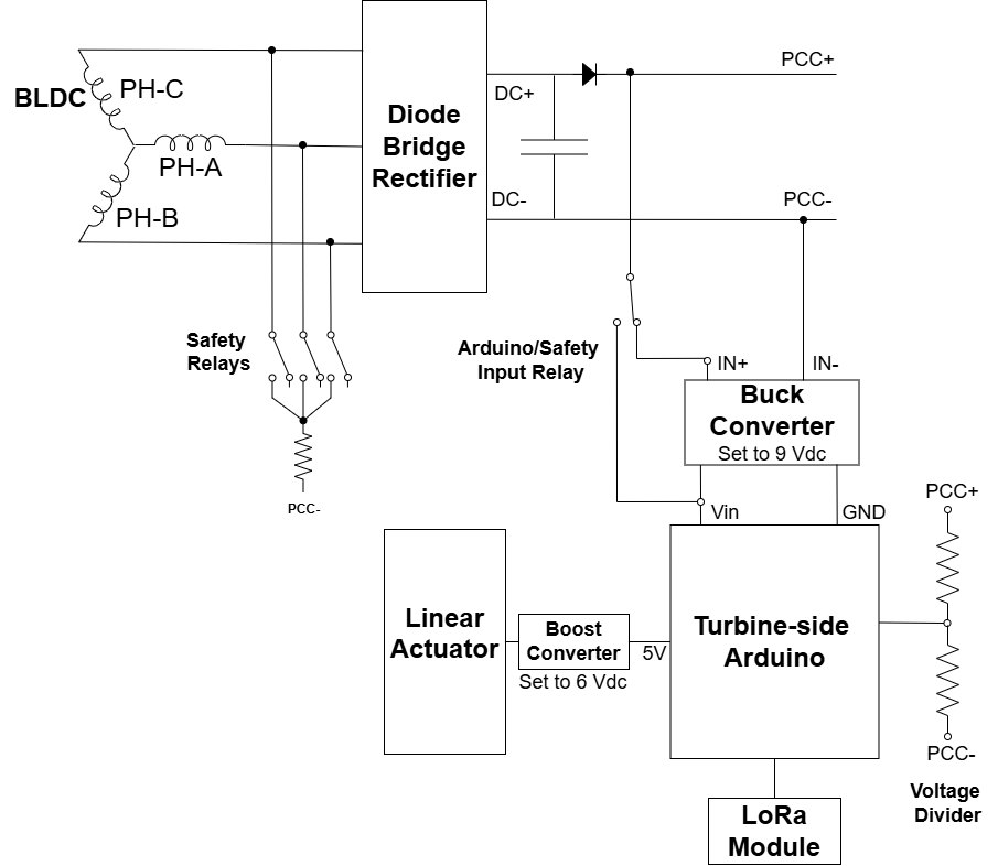
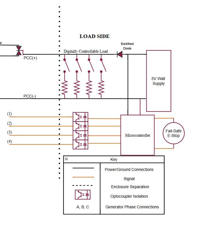
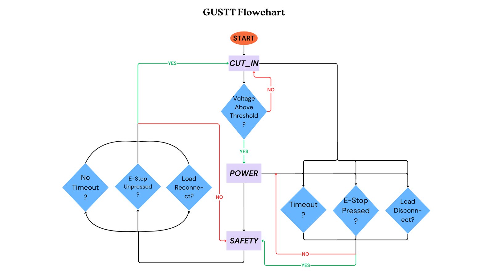
Member of the Power Systems and Controls sub-team for the Wind Turbine Team at Virginia Tech, across both the 2025 and 2026 U.S. Department of Energy Collegiate Wind Competition cycles. On the turbine side a three phase BLDC generator feeds a diode bridge rectifier, then buck and boost converters that hold the controller and linear actuator supplies steady, with safety relays across the generator phases. On the load side a digitally controllable resistive load, a backfeed diode and an optocoupler isolated microcontroller handle load switching and a fail-safe emergency stop, all staged by a control scheme that runs cut-in, power and safety states.

  • BLDC generator
  • Diode bridge rectifier
  • Buck / boost converters
  • Optocoupler isolation
  • Controllable load bank
  • Fail-safe E-stop
  • Safety state machine
Turbine side power electronics with BLDC generator into rectifier, buck and boost converters, safety relays and controller
Turbine side: generator, rectifier, converters, safety relays
Load side schematic with controllable load, backfeed diode, optocoupler isolation and fail safe emergency stop
Load side: controllable load, isolation, fail-safe E-stop
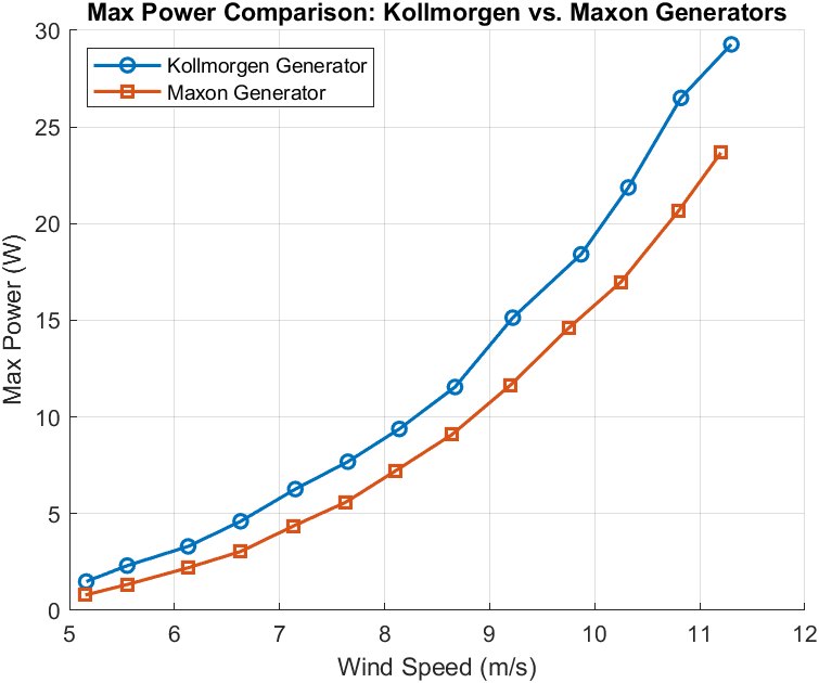
Chart comparing maximum power output of two candidate generators across wind speed
Generator selection by maximum power against wind speed
Control flowchart with cut in, power and safety states and their transition conditions
Control state machine: cut-in, power, safety

Microgrids / Protective relaying / Wind energy / Converters / Real-time simulation

Get in touch

Looking for full-time work in power systems, power electronics, or controls.